- Posted on: 2021-04-06

Intrinsic safety is critical for your ATE
Any test system dealing with electrical energy, thermal energy or gases needs to be able to control the test flow while monitoring one or more parameters to ensure that test conditions remain safe at all times. Occasionally, it is possible that the control software or the operating system hangs for a period of time during which the system cannot guarantee that all parameters remain in a safe range. It is the task of the software “Supervisor” module, along with a hardware watchdog to handle these cases. You can read more about how Symplify handles this “self-monitoring” in this previous blog post.
In this post, we want to focus on other features inside SBX that make our clients task of ensuring the energy is removed from the system and any liquid/gas flow or movement are safely interrupted. Most test equipment includes some form of “interlock” signal that must either be shorted or connected to a TTL (5V) signal supplied by the instrument. Those interlocks usually require extra hardware in the ATS in order to properly use them.
Isolated and “safe” ATE outputs
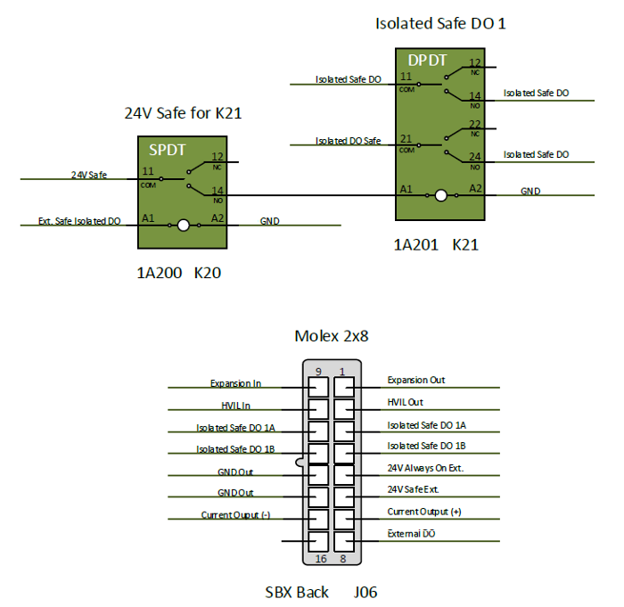
Inside SBX-420C, we offer multiple isolated digital outputs (DO) through standard relays, but those are not tied to the watchdog circuitry so they are not well suited for safety applications when used on their own. What Synovus included in the SBX design is a simple circuit that offers isolated digital outputs that can only be enabled when the system is deemed “Safe”, which includes the Watchdog monitoring.
As you can see, K21 can only be enabled if both the 24V Safe (watchdog, e-stop, external e-stop, etc.) is present and if the corresponding digital outputs from NI9375 are “On”. This makes them perfect to close the interlock circuit of most test equipment while keeping the system safe and voltage levels isolated.
From 12VDC to 240VAC
Another application of this circuit is for clients who need “Safe” 120/240V AC. All the wiring and components in the isolated outputs already support those voltages with up to 8A per line. To safely control a multi-pole contactor or power to the device under test (DUT) without adding external hardware, one simply needs to:
1. Supply 120/240VAC (fused 8A) to pin J06.3
2. Connect pin J06.11 to one of more “Normally Open (NO)” pins on the 24 pins Molex connector
3. Wire the corresponding “Common” pin on the 24pins Molex to the device/equipment
With the addition of a simple jumper wire, you now have access to a power source that is intrinsically safe as it will be cut off if the system becomes unresponsive or if the Supervisor detects over-voltage, over-temperature, etc.
